Simple USB DAC
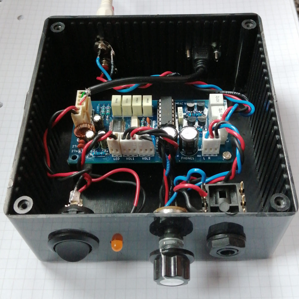
I was looking for a way to stream audio over my home network so I could play music on my stereo from my phone/computer wirelessly - it turns out what I was looking for was quite expensive. So I decided to attempt to make something more affordable and that met my needs exactly. My idea was to make a standalone USB DAC that could be used to drive a line level input and high impedance headphones using one USB connection for power and audio data. The completed unit could then be used as an independent headphone amplifier and/or streamer when combined with a Raspberry Pi running Mopidy
Unfortunately I won’t be properly releasing the CAD files since I made a mistake reading a datasheet which resulted in most of the circuitry being redundant and over-engineered (details below). I do hope to eventually return to this project at some point in the future but for now I’ll just write this article as a reminder to always triple check datasheets before commiting designs to solder!
USB Interface
I’ve never made something that interfaces with USB data lines so I did a bit of research to find out more. I based my design on some guidance from an application note from Silicon Labs
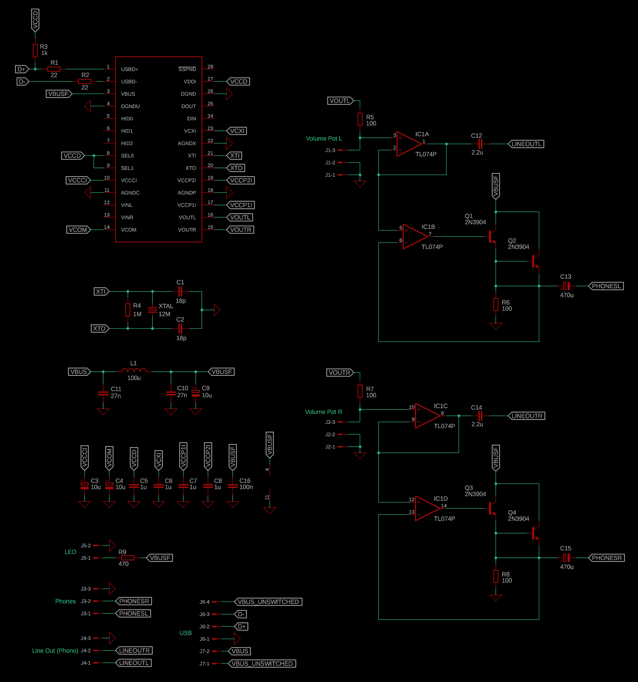
Since the USB Audio Class 2.0 standard uses the lower 1.5Mbps transfer rate (I think?) I elected to disregard the effect of the characteristic impedance of the PCB traces. I used 22R termination resistors on the data lines as well as a 1k pullup on the D+ line. I copied the filter from the application note to limit noise on getting into the DAC’s power rails. I replaced the ferrite bead with an equal value hand-wound inductor (100uH = 42 turns on an FT37-61) - this is not ideal but better than nothing!
I’m not sure how necassary this is or how critical the values of components are but I’d rather err on the side of caution
DAC
After some further reading into the USB Audio Class 2.0 standard I soon found out I was well out of my depth. So I cheated and used an off the shelf USB DAC chip - the PCM2704C. It directly takes the USB data lines outputs an analogue signal. The DAC itself can operate up to 16-bit @ 48kHz stereo which is good enough for my ears
All of its support circuitry is connected as per the datasheet, using good quality film bypass capacitors as recommended
Output Stage
A 10k potentiomter along with a 100R current limiting resistor is placed across the output of the DAC to control the volume. The output of the potentiometer is buffered with an MCP6004 quad opamp to get rid of any loading effects. The line level signal is taken directly from the output of the opamp and its DC offset removed using a good quality film capacitor
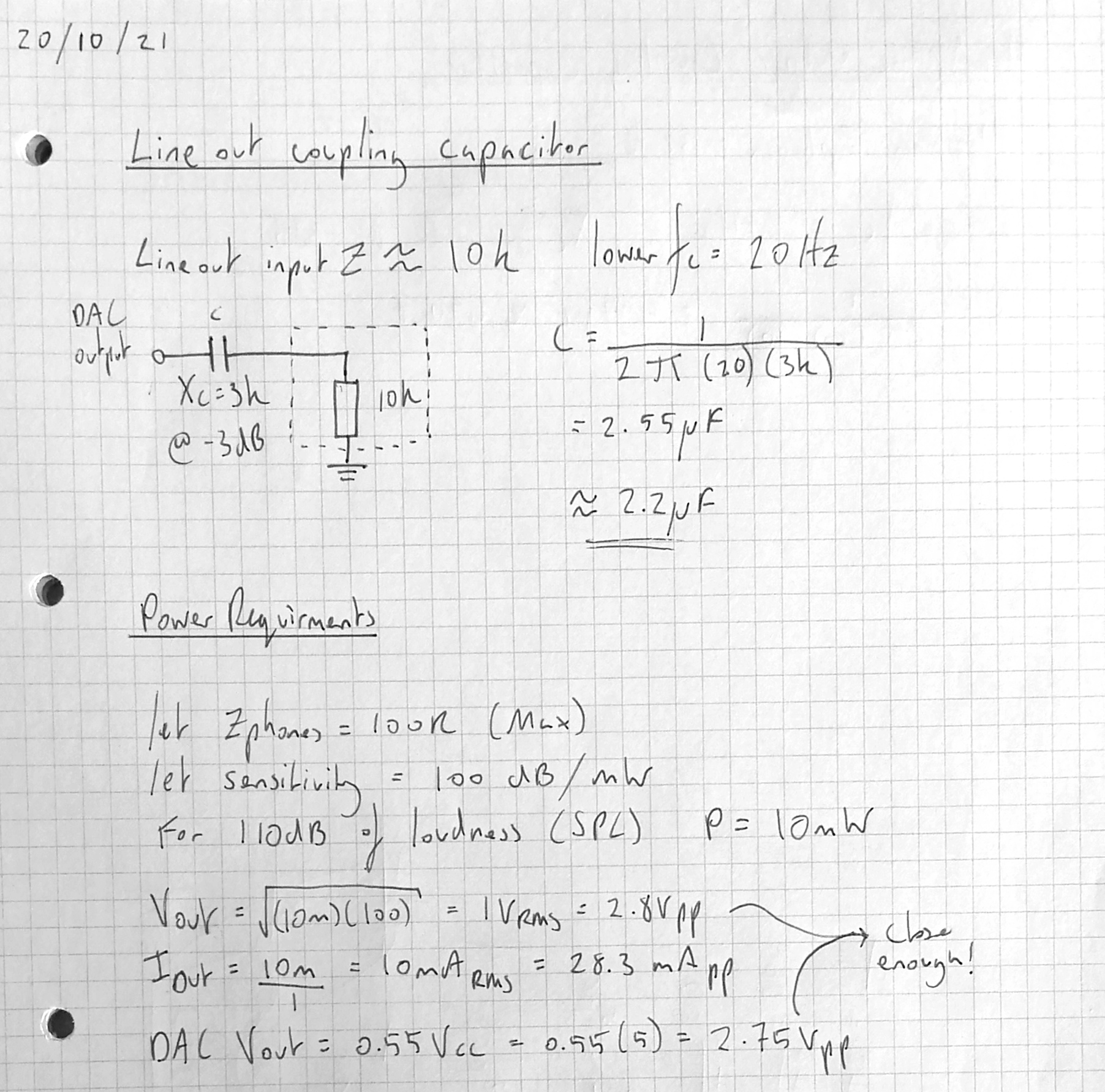
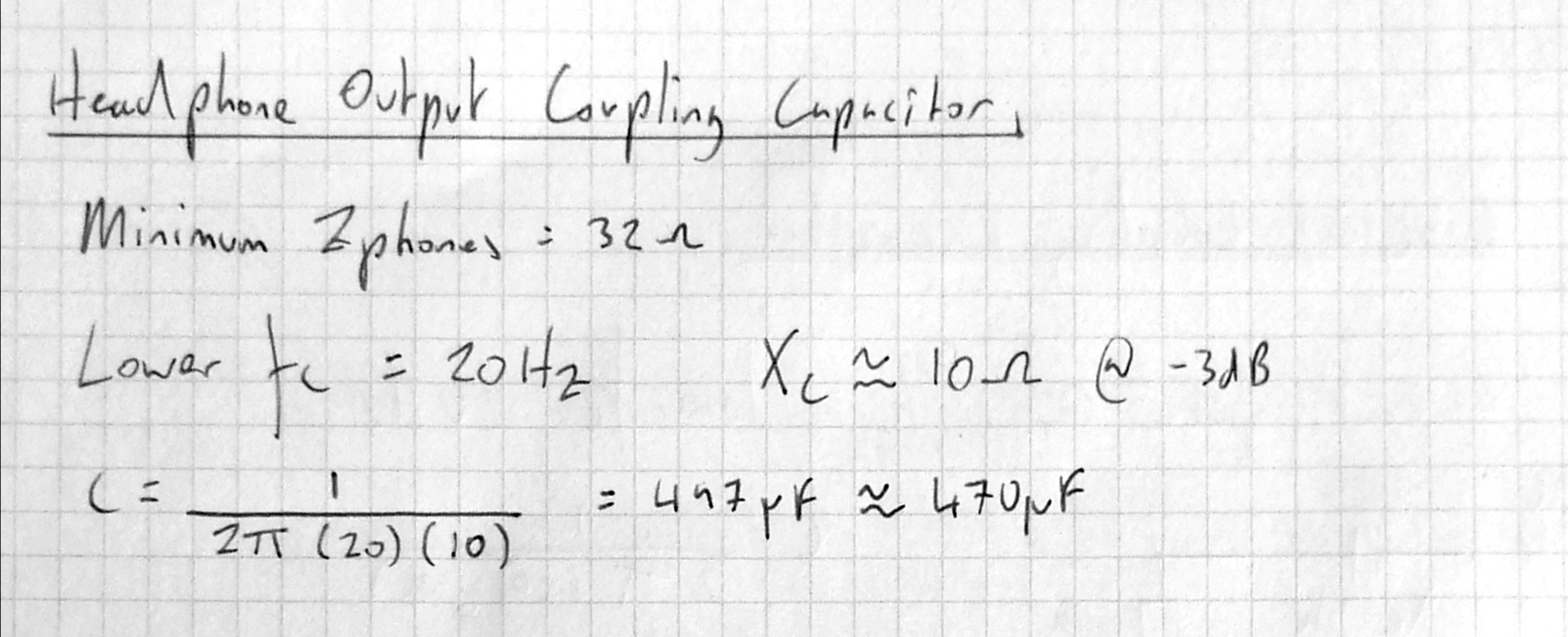
The opamp can only deliver up to 12mA, so I made a darlington pair with two 2N3904 BJTs to bump up the current capability of the headphone output. I put the darlington pair in the feedback path of the opamp in an attempt to reduce any distortion caused by uneven current gain (hfe) between the transistors. To remove the DC offset from the audio signal I used a high quality electrolytic coupling capacitor. A higher value coupling capacitor was needed to maintain the same bass response as the line level output
The output voltage directly from the DAC should be good enough to drive up to 100R headphones - or so I thought.
I made a big mistake when reading the datasheet. The DAC’s output amplitude is quoted as 0.55Vcc - this is the internal regulated Vcc of 3.3V, and not the 5V Vbus. So the output amplitude is actually around 1.8Vpp. I didn’t notice this until I put the board together and measured the output level…
Improvements
If I were to redo this project, I would add a voltage gain stage and use a rail-to-rail opamp in order to drive the headphone output up to 4.75Vpp. As it is it has no problem driving the line level output and normal 32R headphones but it renders most of the circuitry pointless! I’d also look to remove the DC offset of the DAC’s output without use of capacitors in the signal path
Another project that could be spun off from this would be to make a standalone line level USB DAC daughter board for a Raspberry Pi. The current design could be easily simplified down to just the USB DAC chip and its supporting circuitry. Although having said that a higher quality SPI or I2C DAC would probably be more suited to this application