How To Make Your Own Off-Brand Winkie
On Ep. 114 of CheapShow, Paul and Eli found a bizarre French single promoting a failed electronic pin badge called Winkie.
It’s just a badge that alternates between a red and green LED every second. It sounds incredibly dull but somehow it’s not.
I found myself so far down the rabbit hole, I decided to design a clone.
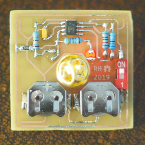
I present to you, Wankie:
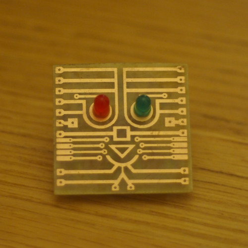
This post will go through how I designed it and how to make your own (if you can etch your own circuit boards…)
Design
I’ve never actually seen a Winkie with my own eyes so the entire design is based on what little info there is online. The most useful source was an episode of Digitiser, where Paul shows a close up of the bottom side. It runs off of two small coin cells, probably LR44s; assuming 5mm LEDs it appears to be 40x40mm; there’s a plastic ring that shorts connections on the corners of the board that influence the winking.
From this the Wankie must:
- Blink two LEDs
- Be 40x40mm
- Run off of two LR44 cells
- Have some “random” influence in the form of conductive tabs on each corner
To achieve this I based my design on a generic 555 timer LED blinker circuit, but using an LMC555 - a low-power CMOS 555 timer that can run on 3V.
For the “randomness” effect, the output pin loops around the whole board with either a ground or 3V connection next to it on each corner. Conductive tabs, made of aluminium foil glued to struts, then short these together when pressed which overrides the output’s influence and lights only one LED. So when you’re wearing the badge it occasionally deviates from lighting alternate LEDs every second.
The design on the front is based on a cleaned up version of the single sleeve by Ivenne (the creator of the CheapShow Magazine!). By using a double-sided circuit board the design and circuit can both etched at the same time.
PCB Layout
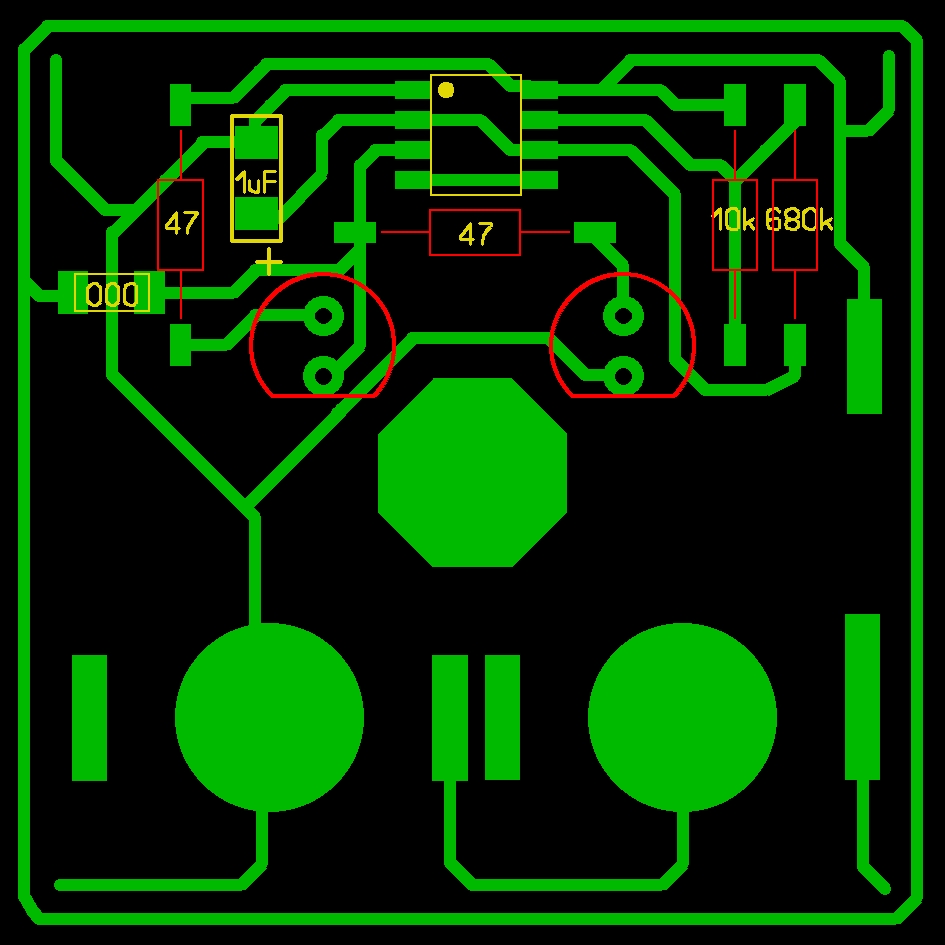
I used a mix of surface mount and through hole components, simply because it’s what I had lying around.
The link below is a PDF with the front design and circuit layout to scale for an A4 page. It also includes an outline for the struts.
I won’t go into detail how to etch boards at home but here’s a few tips for photo-etching a double sided board:
- To make sure both sides are aligned properly, leave a leader of about 25mm at the top and bottom of both transparencies. Line both transparencies up whilst holding them flat and taut, then tape or staple each leader together.
- Cut off a small corner of your transparencies and the laminate. This means you can be sure you’re exposing it the the same way round on each side, it can be easy to lose track of orientation when flipping the board over and peeling off the protective film.
Materials
It’s a bit unorthodox but it is made out of widely-available, standard parts - maybe just not the standard way of using them. Here’s a list of what you need:
Instructions
Since it’s a bit weird and not so obvious from the layout, I’ll go through each step of construction (I’ll assume you have a blank PCB ready to go).
1. Apply a light layer of PCB varnish to the front - it’ll make it last longer. Clear nail varnish works too.
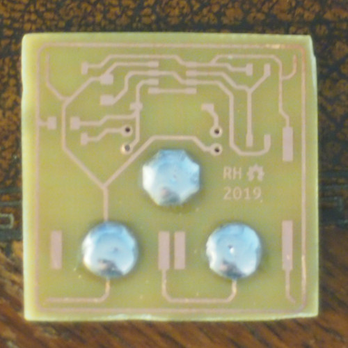
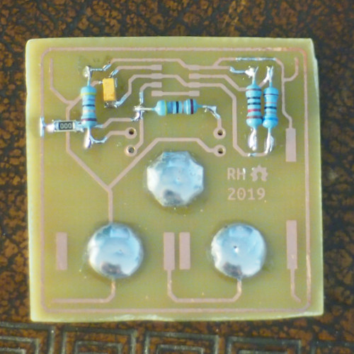
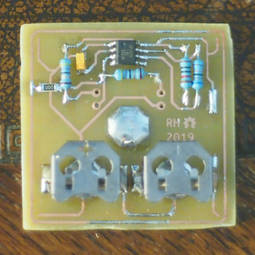
2. Solder the largest pads for the negative cell contacts and the pin back.
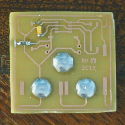
3. Solder the 0 ohm link and the capacitor. If you’re using a soldering iron, to make them sit flush to the board you can tin the pads then use some solder wick to make the pad flat. Tack one lead on and solder other lead then reflow the first lead again.
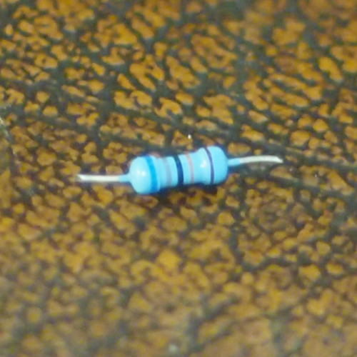
4. Prepare the resistors by cropping each lead to about 4mm. Then solder them to the board.
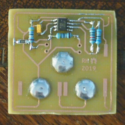
5. Solder the 555 timer. Tin the pads then tack two diagonal pins then reflow all eight pins.
6. Prepare the pads for the cell holders by tinning them and using solder wick to make them flat.
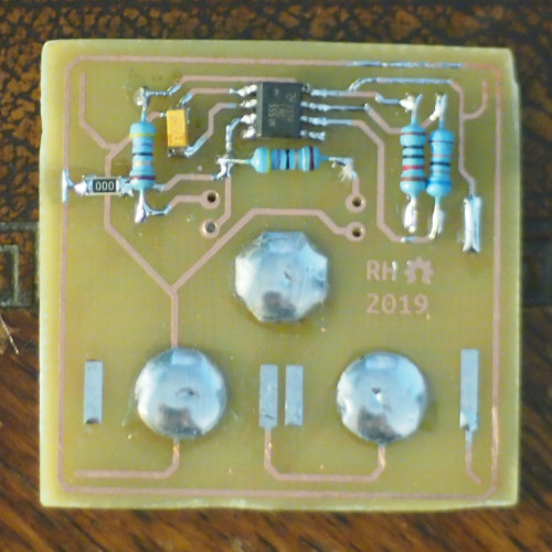
7. Form the leads of the cell holders by gently bending them perpendicular to the body with a pair of small pliers/blunt snips. Crop off the excess. Surface mount versions do exist but I couldn’t find them - use them if you can!
8. Position the cell holder centred with a pair of pliers and flow lots of solder on each lead. They’ll be under a lot of mechanical strain when the cells are in them!
9. To make the pin back, crop one of them to about 4mm then tin the flat side of each. Hold them flush together and place your iron on the cropped side. A hot iron will make this much easier!
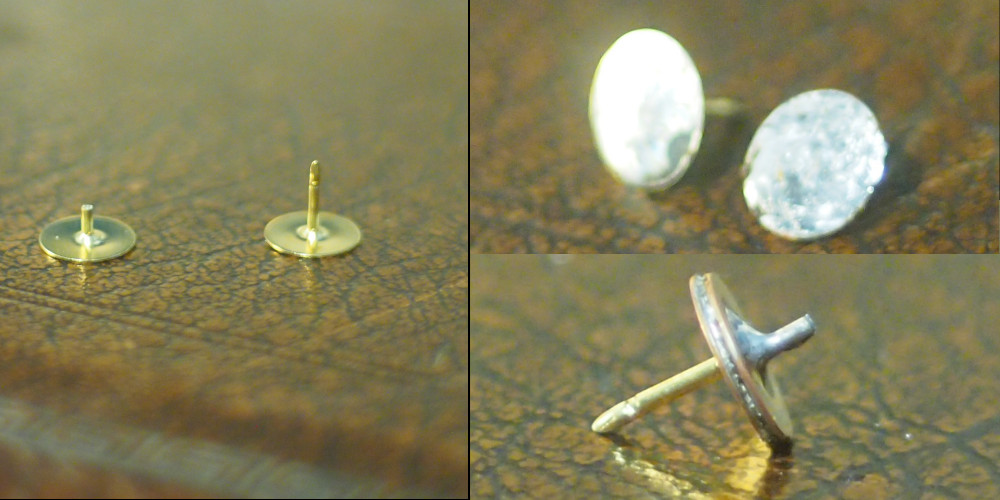
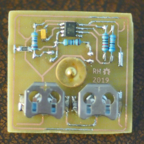
10. Using a pair of pliers to hold the pin back, reflow the central pad and place the pin back in the centre.
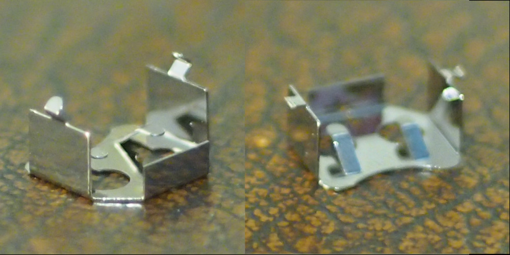
11. Form the leads of the switch by bending them perpendicular to the body with a pair of pliers/blunt snips
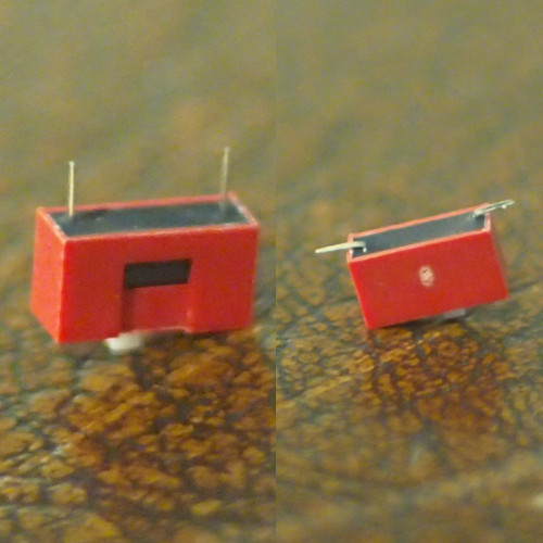
12. Position the switch then tack one end and reflow both sides with a generous amount of solder to make a strong mechanical bond. A dab of super glue on the right side of the switch will also help with this.
13. Solder the LEDs. Make sure they’re flush on front facing side. It should now work!
14. Prepare the struts by cutting them out from your transparency sheet and cutting four small rectangles of aluminium foil onto a paper towel. The foil bits don’t need to be exact - you can crop the edges later with a pair of scissors.
Make a small pool of superglue on the paper towel, then drag the end of each struts through the glue and place it on top of a piece of foil. It should pick it up.
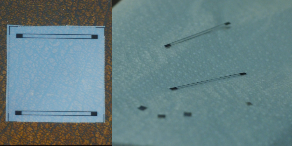
15. Attach the struts by placing them into position (where the foil touches the two corner contacts on each side as shown). Then place a bead of superglue in the middle of the struts and leave to dry.
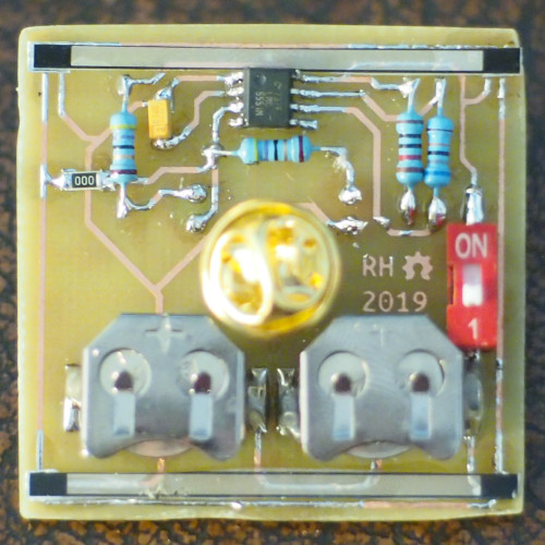
You have made your very own Wankie!
If you have any questions or issues - let me know!