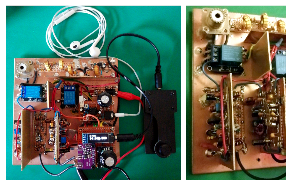
Homebrew 20m QRP CW Transceiver (Part #1)
This post documents the fruits of my first proper attempt at designing a full transceiver from scratch. I should make clear that this isn’t meant to be a guide on how to design a transceiver - I’m not an expert and this is only for fun. All I’m doing here is sharing a few methods for designing radio circuits that work for me and that I can understand. Your mileage may vary!
Update 20/04/2021: a PCB based on this design is coming soon…
Overview
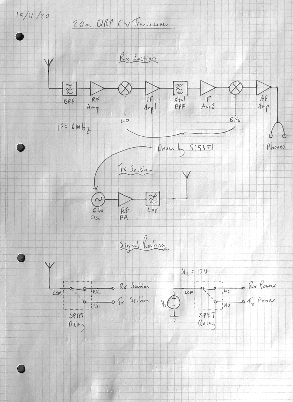
For the receiver my main goals were to make it as sensitive and selective as possible while using readily available disrete components. To achieve this I opted to design a full superheterodyne. I selected an IF of 6MHz since its high enough that a crude bandpass filter will easily knock out any images (which will appear at around 2MHz). It is also low enough that I know I can use simple single transistor amplifiers in the IF stage without any issues
For the transmitter my main aim was efficiency and size since this is going to be a portable radio. To achieve this I opted to use a class E amplifier and aimed for 5W ouptut. Because this is a CW rig any distortion will have negligible effect on the fidelity of the transmitted signal once passed though a suitable the lowpass filter
I have never been able to get a proper analogue VFO to work properly so I decided to stick with my trusty Si5351 clock generator module to generate the LO, BFO and CW signals. To drive the Si5351 module as well as an OLED display and rotary encoder for setting the frequency I used an Arduino Nano. The relays and keying stage are also handled in firmware using an interrupt subroutine
Acknowledgements
A lot of my approach to designing RF circuits is informed by the book Solid State Design for the Radio Amateur
Peter Parker (VK3YE), Pete Juliano (N6QW) and Charlie Morris (ZL2CTM) all make really insightful content about their homebrew experiments which have helped me immensely!
Useful sites
toroids.info is incredibly useful when making toroidal transformers
rf-tools.com is great tool for designing passive filter networks
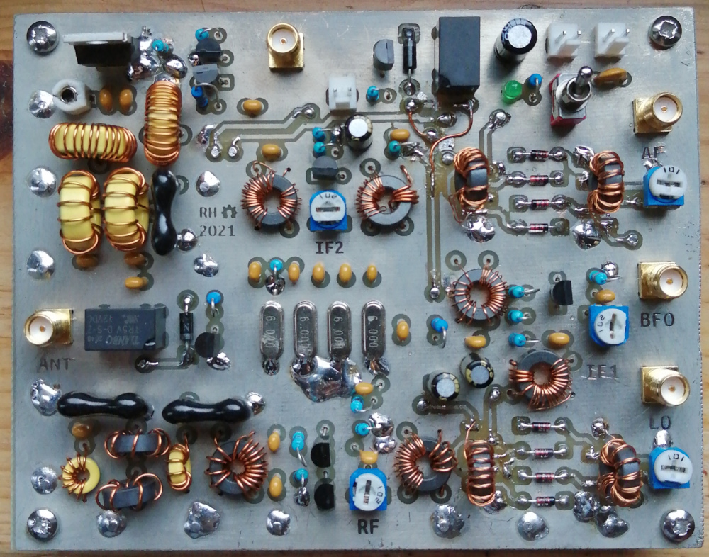
RF Frontend
Bandpass Filter
I used a 3rd order Butterworth filter to attempt to make the passband as flat as possible. As previously mentioned this filter doesn’t have to have a particularly narrow or accurate since any images are going to be 12MHz away from the desired frequency. So I wasn’t too concerned about the slow rolloff associated with the Butterworth topology
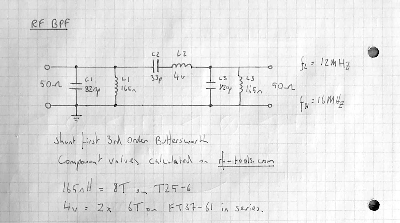
The LC filter calculator on rf-tools.com was used to calculate the component values
It should be kept in mind that stable low-tolerance capacitors should be used for RF filters to work pratically - I stick to NP0 ceramic and silver mica type capacitors
Amplifier
In my experince single transistor amplifiers are a bit hit and miss when operating above 10MHz, so I elected to use a cascode configuration for the RF frontend amplifier since it operates at 14MHz. The cascode configuration reduces the Miller effect that causes the gain to fall off a cliff at high frequencies
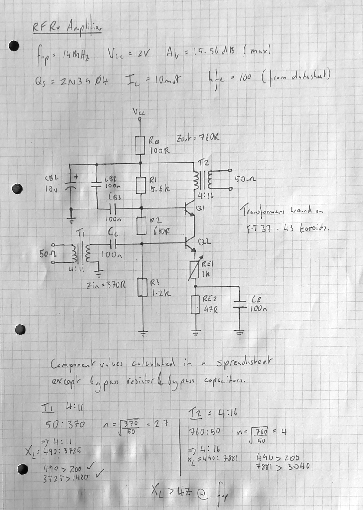
My method for calculating the component values is a mix of ideas and techniques I’ve picked up from various sources that I’ve moulded together over time. After setting the voltage at the emitter of Q2 with respect to ground to one tenth the supply voltage, all of the other values can be found with Ohm’s law. Another trick is setting R3 to be one tenth the impedance “seen” at the base of Q2 (hfe * RE)
I’ve made a spreasheet calculator to make it easier to play around with different parameters, which you can download here:
Cascode Common-Emitter Amplifier Stage Calculator
I split the calculated emitter resitance across two resistors with a capacitor between them to ground to provide some negative feedback at frequency. Using a 1k trimpot for RE1 allows the gain to be set on the fly. With the timmer at 0R, the total current through the transistors (at DC) is around 80mA (12V / 147R) which is well within their current rating
A bypass resistor is connected between 12V and the amplifier to help stabilise the circuit since the coil doesn’t limit current at DC - I use a nominal value of 100R throughout the amplifiers in the receiver. Bypass capacitors are placed across the supply voltage and base of Q1 to help prevent oscillations caused by having an inductive load. A 100n coupling capacitor is placed after T1 to remove any DC offset that may be on the signal which could upset the transistor bias. These values aren’t critical so using standard capacitors will be fine
Impedance Matching Transformers
Toroidal impedance matching transformers are used throughout this radio to couple the various stages with differing input and output impedances together
For T1 we want to “transform” the 50R output of the bandpass filter to the 370R input of the amplifier. This gives a turns ratio of 2.7 which is then used to find integer pairs that (roughly) match this ratio e.g, 4 * 2.7 = 10.8 ≈ 4:11
I use the following rule of thumb: the reactance of the coil should be at least 4 times greater than the impedance you want to match, i.e. Z = 50 ∴ XL >= 200. I’m not sure why this is the case but they do perform much better when compared to having the inductive reactance closer to the actual impedance you want to match
I use toroids.info to calculate the inductive reactance of the coil by selecting the type of toroid, the number of turns and the frequency of operation (which in this case is 14MHz). If the reactance is less than 4 times the impedance you want to match go up to the next highest turns ratio
It’s advantageous to use the least number of turns possible. Having a few different types of toroid to choose from will make this easier. I keep FT37-43, FT37-61, T25-6 and T50-6 toroids in my parts drawer which covers most bases for HF
IF Stage
Amplifiers
I opted to use single transistor common-emitter amplifiers for the IF stage as I know this type of circuit can to operate comfortably at 6MHz
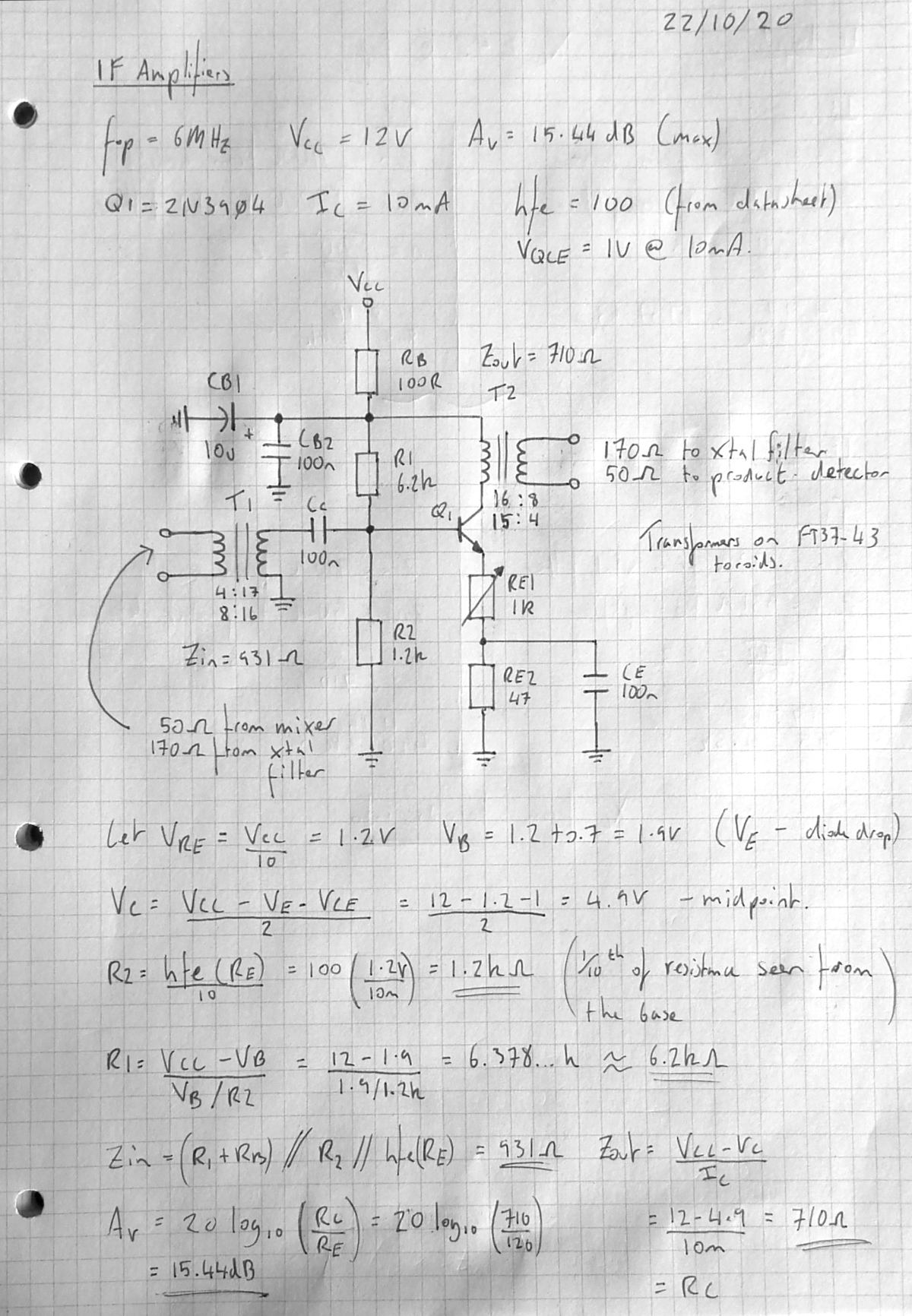
The component values are similar to the RF frontend amplifier since the calculations are essentially the same but account for one less transistor
I’ve made another spreasheet calculator for this circuit, which you can download here:
Common-Emitter Amplifier Stage Calculator
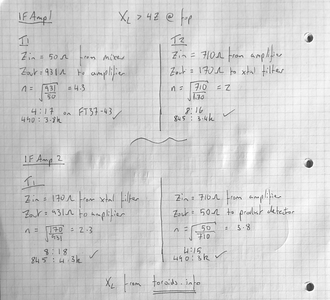
Both IF amplifiers are identical except for their matching transformers which need to match different input and output impedances
Xtal Filter
I used a method by Pete Juliano (N6QW) to make the xtal ladder filter. I can’t find where this was published but I have drawn the schematic out on a piece of paper with his callsign on it so it must be his. I have found that the more effort I put into making a filter the worse it performs. This method is really easy and it works just fine for me
The idea is that if you get four xtals with series resonance frequencies that are within 50Hz of eachother, plugging them into the circuit below should give you a reasonable filter for CW with an input and output impedance of roughly 170R. In this case my filter ended up with a bandwidth of 500Hz. The narrower the bandwidth the better but anything below 750Hz should be good enough
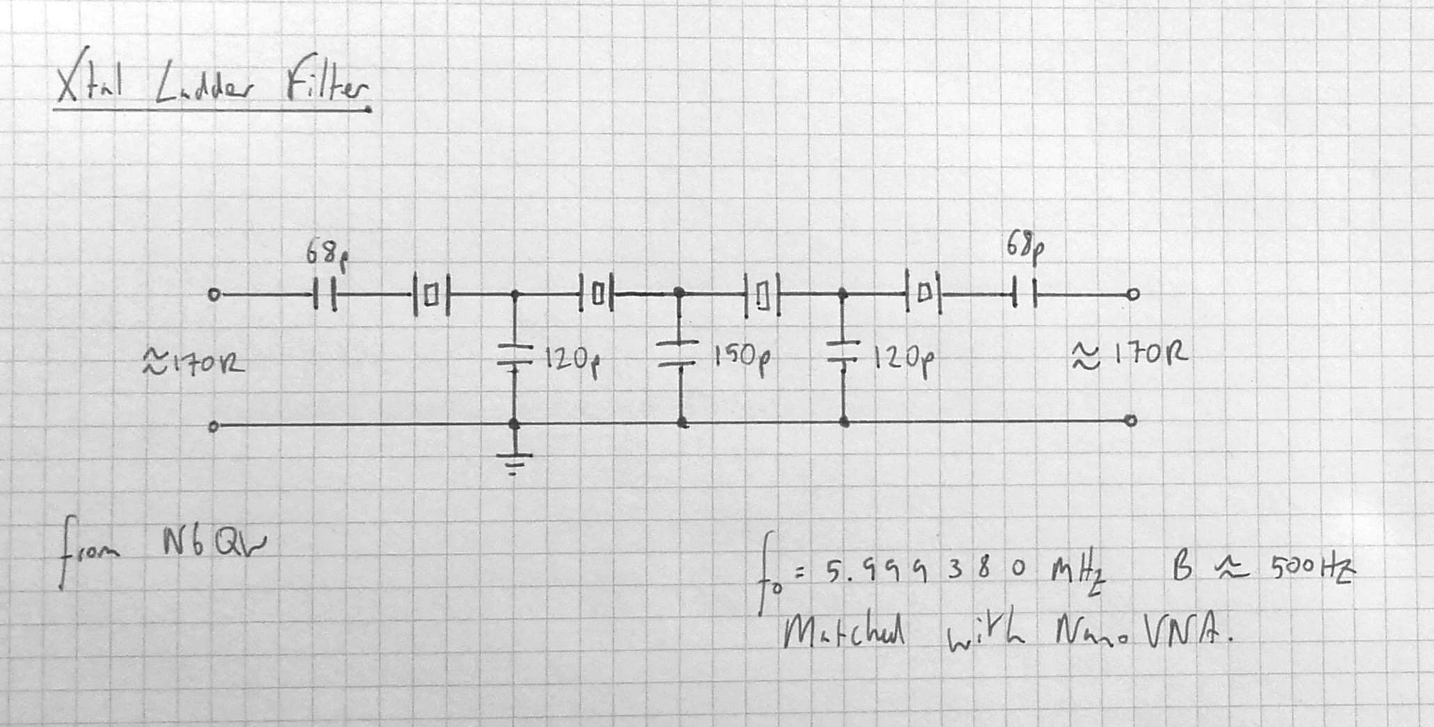
I matched my crystals using a NanoVNA by connecting the input to one leg and output to the other leg - the series resonant frequency is the first peak. This doesn’t account for the mismatched impedance between the xtal and the NanoVNA but I found that it works just as well as more complex methods, such as the one outlined in “Crystal Ladder Filters for All” by Horst Steder (DJ6EV) and Jack A. Hardcastle (G3JIR)
A great benefit of using a digital VFO is that you can very easily offset the LO and BFO frequencies if the resonant frequency of the xtal filter is slightly off from the desired IF
Audio Amplifier
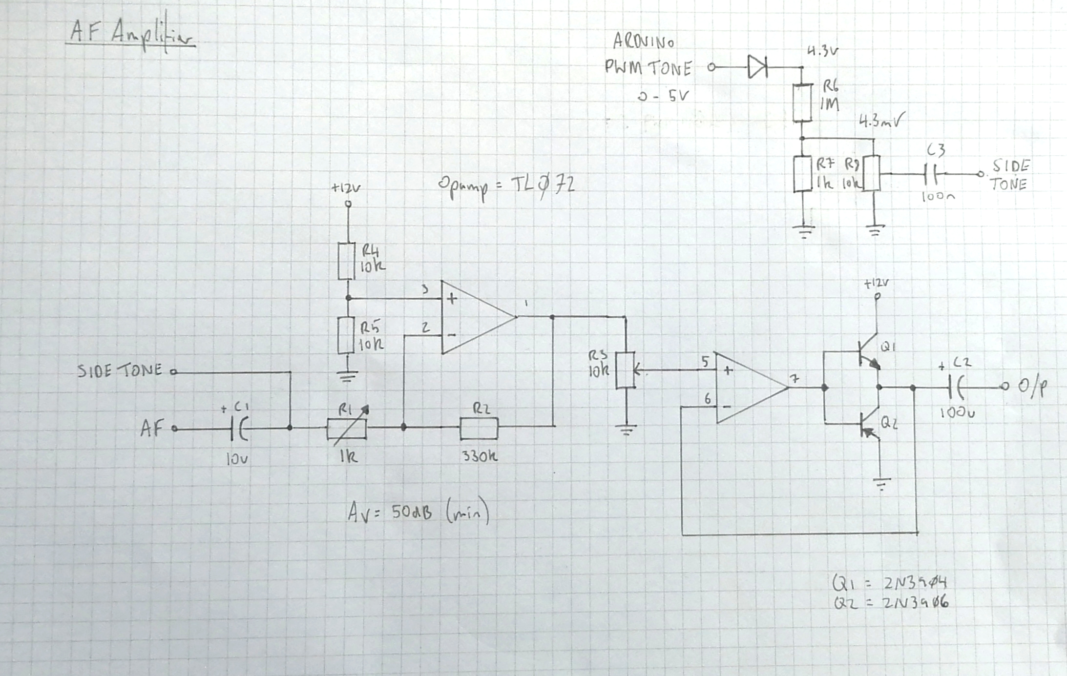
The AF amplifier is based on a TL072 dual opamp and designed to drive headphones of a nominal impedance of 32R. The gain can be increased with with the trimpot (R1) and the final output level adjusted with the potentiometer (R3). To bump up its current output I used a push-pull output stage - placing this in the opamp’s feeback path should remove the majority of any audible distortion. The sidetone generated by the Arduino Nano is attenuated by a diode and a voltage divider down to around 5mVpp. This can then be further adjusted using the potentiometer (R8)
Tx Stage
Class E RF Power Amplifier
A class E power amplifier is potentially incredibly efficient (theoretically up to 99%!) but is difficult to get right. My calculations were taken from “Notes on designing class-E RF power amplifiers” by Bill Slade, which I have put into a spreadsheet calculator can download here:
Class E Power Amplifier Calculator
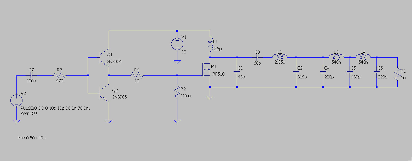
The schematic shown is combined with the lowpass filter described below. From the calculator: Ltotal = L2, RFC = L1, Cmatch = C2, Cres = C3 and Cparallel = C1. The totem pole driver was taken from a design by Charlie Morris (ZL2CTM) in order to drive the MOSFET with the Si5351. It should be noted that the base current limiting resistor (R3) limits the effective bandwidth of the driver as it forms a lowpass filter with the input capacitance of the BJTs (roughly 8pF in this case). There are also two bypass capacitors across the 12V rail that are not shown. Interestingly, while this circuit performs as expected in real life the simulation only outputs uW…
Output Lowpass Filter
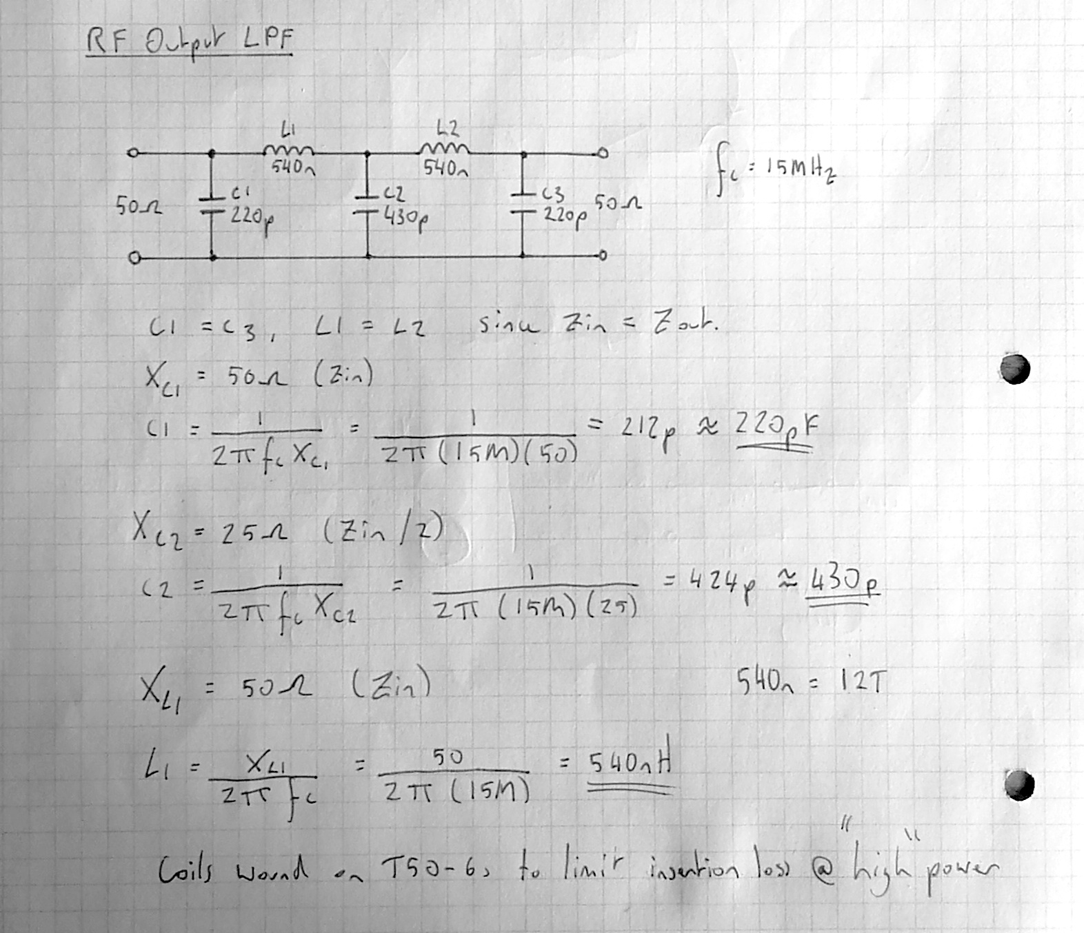
For the output filter I used a simple half-wave lowpass filter with a cut-off frequency of 15MHz. I found the values of C1, C3, L1 and L2 by setting their reactance to 50R at the desired cut-off frequency. C2 was then found by to setting its reactance 25R at the cut-off frequency
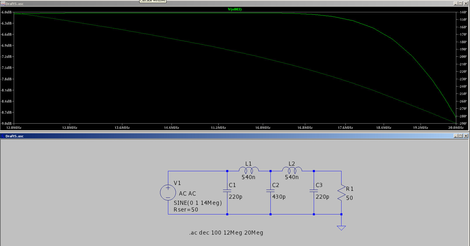
From the simulated bode plot the effective cut-off frequency is actually about 20MHz. In my experience using this method the cut-off frequency is always higher than expected. In this case it shouldn’t matter since the lowest frequency of any significant harmonics will be at 28MHz. If you need a more accurate filter another filter topology may be required
Keying Stage
The keying stage is handled by the firmware. When the key is closed it triggers an interrupt subroutine which enters the transceiver into its transmitting state
LO and BFO signals are enabled
CW signal is enabled
Antenna relay is activated
Power relay is activated
After one second has passed without a key press, the opposite of each action is performed in reverse order (i.e. 4, 3, 2, 1) and the transceiver re-enters its receiving state
Firmware
main.ino
#include <Wire.h>
#include <Rotary.h>
#include <Adafruit_SSD1306.h>
#include <si5351.h>

// Pin defintions
#define morseKeyPin       2
#define encoderSwitchPin  3
#define encoderDataPin    4
#define encoderClockPin   5
#define antennaRelay      6
#define stagePowerRelay   7
#define sidetonePin       8

// Define 14MHz band
const uint32_t bandStart = 14000000;
const uint32_t bandEnd = 14350000;
const uint32_t bandHome = 14060000;

// IBP (reserved section for beacons)
const uint32_t startIBP = 14099000;
const uint32_t endIBP = 14101000;

volatile uint32_t frequency = bandHome; // Frequency is set to band home by default
volatile int8_t cursorPosition = 3; // 1kHz step
const uint32_t intermediateFrequency = 5999200; // ~6MHz IF
const uint16_t beatFrequency = 700;
volatile uint16_t sidetone = 700;

// Manage transmission status/timing
volatile bool transmitting = false;
volatile bool transmissionStateChanged = false;
volatile int keyStroke = false;
volatile bool frequencyChanged = false;
unsigned long lastKeyStroke = 0;

// Intialize rotary encoder
Rotary r = Rotary(encoderDataPin, encoderClockPin);

// Initialize display
Adafruit_SSD1306 display(128, 32, &Wire, -1);

// Initialize DDS
Si5351 si5351;

void setup() {
  // Setup rotary encoder.
  r.begin();
  pinMode(encoderSwitchPin, INPUT_PULLUP);

  // Setup sidetone
  pinMode(sidetonePin, OUTPUT);

  // Setup relays
  pinMode(antennaRelay, OUTPUT);
  pinMode(stagePowerRelay, OUTPUT);

  // Setup morse key
  pinMode(morseKeyPin, INPUT);
  pinMode(LED_BUILTIN, OUTPUT);
  attachInterrupt(digitalPinToInterrupt(morseKeyPin), onMorseKeyChange, CHANGE);

  // Setup DDS
  si5351.init(SI5351_CRYSTAL_LOAD_8PF, 0, 0);
  si5351.set_correction(178700, SI5351_PLL_INPUT_XO);      // Set to specific Si5351 calibration number
  si5351.set_pll(SI5351_PLL_FIXED, SI5351_PLLA);
  si5351.drive_strength(SI5351_CLK0, SI5351_DRIVE_8MA);
  si5351.drive_strength(SI5351_CLK1, SI5351_DRIVE_8MA);
  si5351.drive_strength(SI5351_CLK2, SI5351_DRIVE_8MA);

  // Setup display
  display.begin(SSD1306_SWITCHCAPVCC, 0x3C);
  updateDisplay();

  // Set default
  stopTransmitting(); // Enter Rx mode.
  updateOscillators(); // Set frequencies
}


void loop() {
  if(!transmitting) {
    unsigned char result = r.process();
    if (result != DIR_NONE) {
      if(digitalRead(encoderSwitchPin) == HIGH){
        updateFrequency(result);
      } else {
        updateCursorPosition(result);
      }
    }
  }

  if(transmitting) {
    if(keyStroke) {
      lastKeyStroke = millis();
      keyStroke = false;
    } else {
      if(millis() - lastKeyStroke > 1000 && digitalRead(morseKeyPin) == HIGH) {
        // 1s since last keystroke and key is up.
        stopTransmitting();
      }
    }

    if(digitalRead(morseKeyPin) == LOW) {
      // Key down - play sidetone, enable CW oscillator
      tone(sidetonePin, sidetone);
      si5351.output_enable(SI5351_CLK2, 1);
      digitalWrite(LED_BUILTIN, HIGH);

    } else {
      // Key up - stop sidetone, disable CW oscillator
      noTone(sidetonePin);
      si5351.output_enable(SI5351_CLK2, 0);
      digitalWrite(LED_BUILTIN, LOW);
    }
  }

  if (frequencyChanged) {
    updateDisplay();
    updateOscillators();
    frequencyChanged = false;
  } else {
    if (transmissionStateChanged){
      if(!transmitting) {
        stopTransmitting();
      } else {
        startTransmitting();
      }
      updateDisplay();
      transmissionStateChanged = false;
    }
  }
}

void onMorseKeyChange() {
  // Handles morse key down
  if(!(frequency <= startIBP && frequency >= endIBP)) {
    if(digitalRead(morseKeyPin) == LOW) {
      if(!transmitting) {
        transmitting = true;
        transmissionStateChanged = true;
      }
    }
    keyStroke = true;
  }
}

void updateOscillators() {

  // Set local oscillator frequency
  si5351.set_freq((long long unsigned)((frequency - intermediateFrequency) * 100), SI5351_CLK0);
  //si5351.set_freq(1000000000ULL, SI5351_CLK0);

  // Set BFO frequency
  si5351.set_freq((unsigned long long)((intermediateFrequency - (beatFrequency / 2)) * 100), SI5351_CLK1);

  // Set CW frequency
  si5351.set_freq((unsigned long long)frequency, SI5351_CLK2);
}

void startTransmitting() {
  // Disable LO and BFO
  si5351.output_enable(SI5351_CLK0, 0);
  si5351.output_enable(SI5351_CLK1, 0);

  // Set relay control signals (active low)
  digitalWrite(stagePowerRelay, HIGH); // Turn on Tx stage, turn off Rx stage
  // Delay?
  digitalWrite(antennaRelay, HIGH); // Antenna switched into Tx output

  transmitting = true;
  transmissionStateChanged = true;
}

void stopTransmitting() {
  // Disable CW
  si5351.output_enable(SI5351_CLK2, 0); // Make sure CW oscillator is disabled.

  noTone(sidetonePin); // Make sure sidetone is disabled.

  // Set relay control signals (active low)
  digitalWrite(stagePowerRelay, LOW); // Turn off Tx stage, turn on Rx stage
  // Delay?
  digitalWrite(antennaRelay, LOW); // Antenna switched into Rx input

  // Enable LO and BFO
  si5351.output_enable(SI5351_CLK0, 1);
  si5351.output_enable(SI5351_CLK1, 1);

  transmitting = false;
  transmissionStateChanged = true;
}
rotary-encoder.ino
void updateFrequency(unsigned char direction) {
  // Update frequency with step dependent on cursor position.

  if(direction == DIR_CW){
    if(cursorPosition > -1) {
      frequency = frequency + pow(10, cursorPosition);
    } else {
      sidetone += 50;
    }
  } else {
    if(cursorPosition > -1) {
      frequency = frequency - pow(10, cursorPosition);
    } else {
      sidetone -= 50;
    }
  }

  // Clamp frequency if out of band limit.
  if (frequency < bandStart) {
    frequency = bandStart;
  }

  if(frequency > bandEnd) {
    frequency = bandEnd;
  }

  // Clamp sidetone
  if(sidetone < 300) {
    sidetone = 300;
  }

  if(sidetone > 900) {
    sidetone = 900;
  }

  frequencyChanged = true; // Display and oscillators will be updated on next loop.
}

void updateCursorPosition(unsigned char direction) {
  if(direction == DIR_CW){
    cursorPosition--;
  } else {
    cursorPosition++;
  }

  // Clamp cursor position if outside of acceptable range.
  if (cursorPosition < -1) {
    cursorPosition = -1;
  }

  if(cursorPosition > 5) {
    cursorPosition = 5;
  }

  frequencyChanged = true; // Display and oscillators will be updated on next loop.
}
display.ino
void updateDisplay() {
  String frequencyString = String(frequency);
  String formattedFrequency = frequencyString.substring(0, 2) + "." + frequencyString.substring(2, 5) + "." + frequencyString.substring(5);
  display.clearDisplay();

  display.setTextColor(WHITE);
  display.setTextSize(1);

  if(transmitting) {
    display.setCursor(4, 0);
    display.println("TX");
  } else {
    display.setTextSize(1);
    display.setCursor(4, 0);
    display.println("CW");
    display.setCursor(20, 0);
    display.println(sidetone);
    display.setCursor(38, 0);
    display.println("Hz");

    if(cursorPosition == -1 && !transmitting) {
      display.setCursor(29, 3);
      display.println("_");
    }
  }

  display.setTextSize(2);

  display.setCursor(4, 13);
  display.println(formattedFrequency);

  if(cursorPosition > -1 && !transmitting) {
    uint8_t cursorOffset = 1;
    if(cursorPosition < 3) {
      cursorOffset += 1;
    }
    display.setCursor(4 + (7 - cursorPosition + cursorOffset) * 12, 18);
    display.println("_");
  }


  display.display();
}